How Power Electronics Work
Calnetix has created a detailed white paper explaining how power electronics work. To download a copy, click here.
Excerpt from Calnetix’s white paper entitled, “General Overview of How Power Electronics Work”:
Calnetix’s Vericycle™ Bidirectional Drives typically interface with high-speed Permanent Magnet Synchronous Machines (PMSM). The power electronics can be configured for a variety of PMSM pole numbers, including more complex, higher pole configurations. On the utility side, Calnetix power electronic drives are capable of interfacing with U.S. and international power networks that are within the voltage/frequency range defined in our specifications.
Power Electronics Architecture
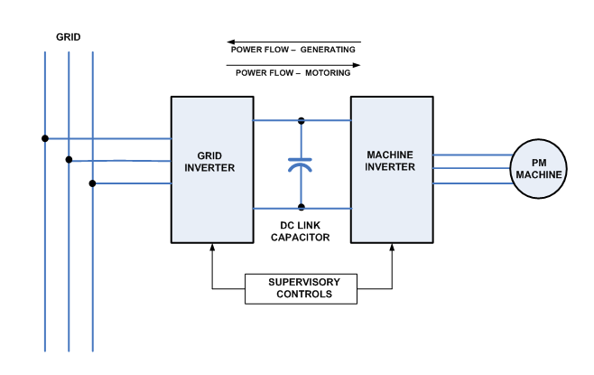
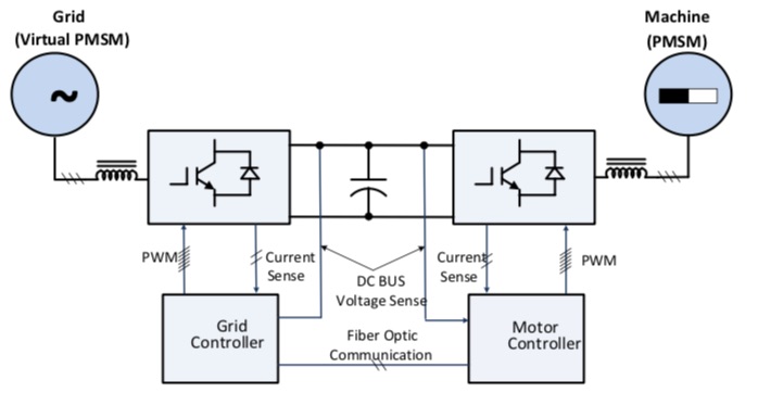
Calnetix’s power electronics power architecture has a very simple hardware configuration consisting of two identical inverter modules interconnected by a DC link capacitor. The DC link capacitor provides a low voltage ripple DC energy buffer for the modules. Both power electronic modules are similar in construction and configuration. Therefore, Vericycle™ drives are capable of bidirectional power flow operation (motoring mode or generating mode).
The supervisory controls of power electronic modules automatically assign different functional modes of operation to the modules based on the system application. The power electronic module that is connected to the utility grid assumes an active rectification role for motor drive applications and assumes a grid tie inverter role for generating applications. The power electronic module that is connected to the motor assumes variable voltage and frequency inverting mode for motor drive applications and assumes variable voltage and frequency active rectification mode for generating applications.
Figure 1 illustrates the basic building block of the Vericycle™ power electronics.
In generating mode, high-frequency AC power, generated from the machine, is converted to regulated DC power by the machine side inverter thus charging the DC-Link capacitors. The machine side inverter uses field oriented controls and maintains current to be sinusoidal, thus optimizing the power draw from the machine while maintaining optimum power conversion efficiency. This DC power is then inverted to an alternating current of either 50 Hz or 60 Hz to pass on to a commercial AC power grid (utility grid).
In motoring mode, 50 or 60 Hz AC power from utility grid is converted to regulated DC power by the grid side inverter in the active rectification role, thus charging the DC-Link capacitors. Energy from the DC-Link is then inverted by the motor side inverter to 3 phase variable –voltage and variable-frequency AC power to drive the PMSM.
Supervisory Controller Architecture
Calnetix has developed a simple and robust supervisory control incorporating a sensorless algorithm to control both power electronic stages that is stable across a wide range of operating conditions of voltage and frequency. The control has a good tolerance of the grid voltage unbalance and waveform distortion. Not using a speed, position or voltage sensor in the system design provides an important hardware simplification in design of PMSMs. It also resolves most common technical challenges associated with electrical noise and high voltage isolation issues.
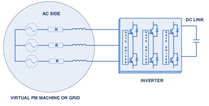
The controller works on principles of the sensorless field oriented algorithm utilizing a Space Vector Modulation (SVM) scheme to control both grid and machine inverter stages. In the case of grid inverter control, the grid is assimilated to a virtual PMSM with impedance matching the machine resistance and inductance given by filter inductance, shown in Figure 2. The Back Electro Motive Force (Back EMF) is considered to be the grid RMS voltage.
The grid side power electronic module is connected to a three-phase grid through one series inductor per phase, shown in Figure 3. The inductor value and the switching frequency of the inverter are optimized to minimize the harmonics of the fundamental frequency entering the grid system. The motor side power electronic module is connected to a three-phase machine through one series inductor per phase. The inductor value and the switching frequency of the inverter also are optimized to minimize the harmonics of the fundamental frequency entering the motor.
A sensorless field oriented control (FOC) with space vector modulation scheme uses a virtual flux estimator together with a phase lock loop (PLL). This offers better noise immunity compared to the commonly used sensed voltage methods commonly used in other power electronic systems. The PLL is able to track grid frequency and voltage angle smoothly, which allows the control to follow the voltage waveform, resulting in a near unity power factor- power flow to the grid.
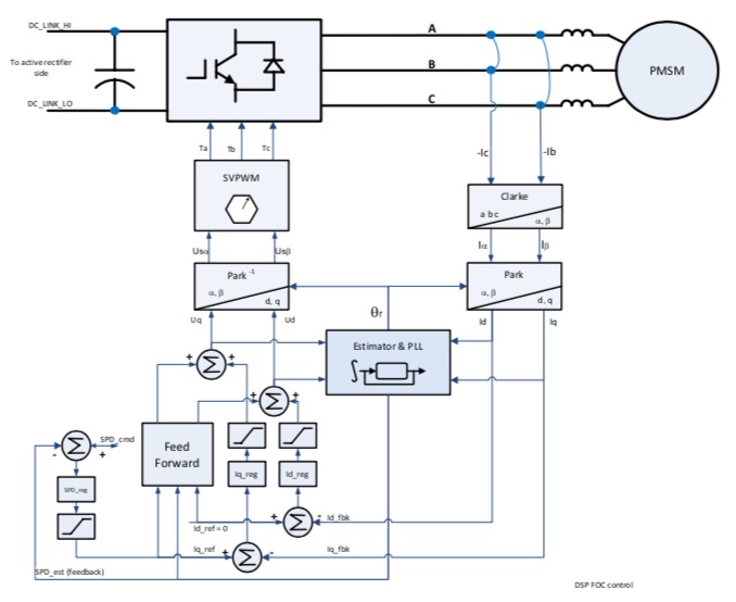
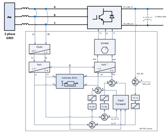
The close loop regulation control algorithm for the module is very similar and is implemented by two major control loops- inner current control and outer voltage or speed control. The outer voltage control (or speed) is used to regulate the DC bus voltage to the predefined value. The inner current loop is used to regulate the magnitude and phase angle of the current to and from the grid or motor. D-axis and Q-axis currents are de-coupled and then regulated separately by current controllers. The primary aim of the control is to transfer current (power) from DC bus to the grid with unity power factor, and vice versa. The reactive current (power) can also be adjusted if required through the D-axis variable inside the control loop. Figure 4 and Figure 5 show the basic control blocks within the controller.
The control function also includes interface communication, PWM commutation, annunciation and protection for critical conditions, such as over current, over voltage, over speed and over temperature.
