Heteropolar Magnetic Bearings
This is an excerpt from "How Magnetic Bearings Work" document. To read the preceding section click here.
In realistic turbomachinery application the object, a turbomachinery rotor, normally spins about its axis Z (directed out of page in Fig. 7) and this brings other complications. To discuss those complications, we will focus only on the bias field for now (for simplicity) and redraw Fig. 7 using 'North' and 'South' designation for the electromagnet poles instead of arrows showing the field direction. (The convention is that the magnetic field is coming out of the 'North' Pole and returns into the 'South' pole).
Two symmetric patterns of the bias poles are possible as shown in Figs. 8a and 8b. In either case, a point on the object (rotor) will see changes of the bias magnetic field polarity when the rotor spins: NN-SS-NN-SS in case of Fig. 8a and N-S-N-S-N-S-N-S in case of Fig. 8b. A complication arises when the rotor material is not only magnetically permeable but also electrically conductive, and this is normally the case in practical rotating machines. This is because rotors spinning at high speeds experience high mechanical stresses and while there are some materials that are magnetically permeable but not electrically conductive, such as ferrites, they are not sufficiently strong mechanically. These considerations make magnetically-permeable ferrous steels a material of choice for the rotors, and they are electrically conductive.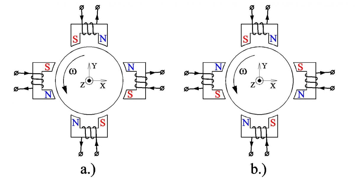 FIG. 8
When a rotor spins in a non-uniform magnetic field such as shown in Figs. 8a and 8b, each point of the rotor sees time-periodic magnetic field variations. In Fig. 8a the frequency of the main field harmonic will be 2f and in Fig. 8b it will be 4f, where f is the frequency of rotor rotation in revolutions per second. According to Faraday's law, these periodic changes of the magnetic field cause periodic voltages, which, in case of conductive rotors, cause eddy currents in the rotors.
One of the unpleasant outcomes is that eddy currents generate heat in the rotor and cause mechanical drag.
The other outcome is even more unpleasant. As any other electrical currents, eddy currents induced in a spinning rotor produce their own magnetic field, which gets superimposed on the external magnetic field. The end effect is known as a skin effect - the net magnetic field gets expelled from most of the rotor instead of very thin (skin-deep) layer on the surface of the rotor. The thickness of this layer can be estimated using the equation (4) below:
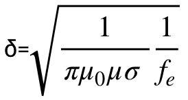 (4)
(4)
Where µ and σ are permeability and conductivity of the rotor material respectively and fe is an equivalent electric frequency, which is equal twice the rotor spin frequency for the arrangement shown in Fig. 8a and four times for the arrangement shown in Fig. 8b.
For example, electrical silicon steel has µ≈4500 and σ≈2.5⋅106 S/m. If the rotor has a bias pole arrangement shown in Fig. 8a and spins at 30,000RPM (f=500Hz, fe=1000Hz), the skin depth would be only 0.15mm (0.006"). Since the magnetic flux density in ferrous materials is limited by material saturation to approximately 1.5T for regular steels and about 2.1T for cobalt alloys, very limited magnetic flux will be able to flow in this thin surface layer. In other words, the bias flux, and similarly, the control flux, will be expelled from the rotor and the bearing will cease to function at speed.
In order to avoid expelling the magnetic flux from a spinning rotor, rotor portions interacting with stationary parts of magnetic bearings are normally made out of electrically insulated steel laminations stacked in the axial direction. The electrical insulation between the laminations breaks up the paths for eddy currents. Note that there still will be eddy currents within each lamination and the radial bearing capacity will start deteriorating once the skin depth calculated using equation (4) becomes smaller than the lamination thickness.
The radial magnetic bearings illustrated in Figs. 7 and 8 are called heteropolar because the polarity of the bias poles changes around the rotor circumference. This is a consequence of the magnetic fluxes being constrained to one plane normal to the rotation axis (magnetic flux lines always form closed loops - if they exited at one pole they always will have to come back in the other, and in case of heteropolar bearings both poles lie in the same plane).
Click here to read the next section.