Magnetic Bearing Controllers
for High Operating Speed and Low Power Loss
Advantages
Although there are similarities between magnetic and conventional bearings, the use of active control allows a magnetic bearing system to incorporate many desirable features that are just not possible for conventional bearing systems. A few of the many features available in Calnetix’s MBCs include:
History Logs
The MBC stores two separate history logs to non-volatile memory – one for events and faults and the other one for emergency shutdown. The event and fault log include time/date stamps, spin speed and other key data. This log also stores events, such as levitate, delevitate, rotation start and stop, sensor calibration, parameter file update, firmware update, rotor drop, drop counter reset, run time counter reset and power up.
In the emergency shutdown log, there are ten data buffers that record a brief time history of key data items whenever a fault is generated while spinning. These data buffers data are recorded to non-volatile memory and can be used for troubleshooting should a fault happen during operation.

Gain Scheduling
Another unique feature of magnetic bearings is the ability to selectively change the stiffness and damping characteristics of the bearings as a function of spin speed. Although spin speed is the independent variable that is typically used for gain scheduling in industrial machines, other variables available to the controller can also be used, if necessary, for a particular design problem. The unique benefits include:
-
More robust vibration control for machines with significant gyroscopic effect
-
Improved machine aerodynamic performance when pressure ratio is used as the gain scheduling parameter in a machine with significant fluid film forces associated with a compressor or turbine
Customer Interface
Customer interaction with the Calnetix MBC is through a Digital I/O interface and a Serial Communication interface. The Digital I/O interface is a hard wired, opto-isolated interface with four inputs and four outputs. The typical input commands are levitate rotor, fault reset and automate self-calibration. The typical output commands are system ready and alarm/trip.
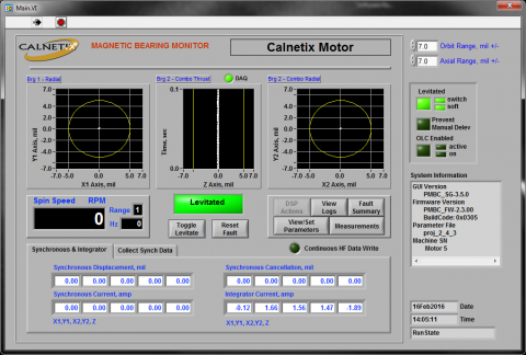
The MBC has two serial communication ports. One is for the Calnetix Service GUI (Graphical User Interface), and the second is a user interface port. The user interface port provides selected register access for a user developed PLC system controller using standard Modbus commands, which allows a user to request operating status and data as needed. The Calnetix Service GUI provides a comprehensive interface and is used for programming and for remote monitoring and diagnostics of the system.
Fault Monitoring
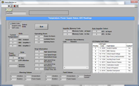
During the operation of the AMB system, the MBC constantly monitors key variables, such as position, current, temperature and others to ensure that the machine and the AMBs are operating as desired. Limits for these variables are established between Calnetix and the customer. Most variables have two limits – a warning level and a fault level. Many of the faults are filtered so that the fault condition must persist for a certain amount of time before a fault is issued. When a limit is exceeded for the specified amount of time, either a warning or fault is issued so that the customer’s system control can take the appropriate action.

Synchronous Cancellation
Since AMB systems apply actively controlled dynamic forces to the rotor, they can do more than just supply stiffness and damping. One of the most important and unique features of AMBs is synchronous cancellation. This type of cancellation also goes by other names, such as Automatic Balancing Control (ABC), Adaptive Vibration Control (AVC), Adaptive Vibration Rejection (AVR), and Unbalance Force Rejection Control (UFRC, is the generic term used by ISO 14839-1).
The cancellation signal for UFRC can be determined by adaptively multiplying the synchronous signal by a suitable influence coefficient matrix (developed either analytically or by measurement). This approach is required for the traverse of the rotor rigid body modes and can be used for higher speeds as well. For speeds above the rigid body mode frequencies, UFRC can be as simple as adaptively subtracting the measured synchronous displacement from the sensor signal before presenting it to the controller. With no synchronous component in the control signal, the controller produces no synchronous current, and therefore, the rotor spins about its inertial axis.
In some type of machines, it is important to reduce synchronous displacements. A rotating force is added by the magnetic bearing with an amplitude and phase that will reduce the synchronous displacement to near zero at up to two axial locations on the rotor. This type of cancellation also goes by names, such as peak of gain control and Unbalance Force Counteracting Control (UFCC is the generic term used by ISO 14839-1).
There are also approaches to supply synchronous damping to assist the traverse of a bending mode in a supercritical machine. This has been called Synchronous Damping control (SDC) and Optimum Damping Control (ODC).
The benefits of synchronous cancellation include:
-
Significantly reduces the effect of mass imbalance on the system
-
Reduces synchronous forces and transmitted vibration to the machine housing
-
Reduces actuator power and dynamic load requirements
PRODUCTS
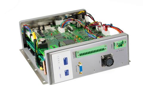
Calnetix currently produces two different MBC platforms in the Insight™ series and one in the Concurrence™ series. MBCs are classified by amplifier reactive power. For instance, the Insight™ 3600 has an amplifier capacity of 3600 V-A per channel and the Concurrence™ 9600 has an amplifier capacity of 9600 V-A per channel. As machine size or dynamic force requirements increase, the required amplifier capacity increases. The digital signal processor is the same across all MBC platforms regardless of size or speed of the machine. Of course, the control algorithm (compensator) is different for the different machines, so the parameter file that defines the compensator is installed in the MBC flash memory using the Calnetix Service GUI. The three Calnetix MBCs are shown and described below.
Insight™ 804
Insight™ 3600
Concurrence™ 9600
Insight™ 804
-
Bearing driven by controller: PM-biased homopolar
-
Input voltage: 144 VDC
-
Maximum continuous current output: 3 A
-
Amplifier current rating: 6 A
-
Bus voltage: 144 VDC
-
Cooling method: Liquid (cold plate)
-
Dimensions: 10x8x3 inches

Resources
View More
White Paper
How A Magnetic Bearing Controller Works
White Paper
How Magnetic Bearings Work
Advantages
Advantages of Magnetic Bearings
Technical Paper
Transient Simulation of Magnetic Bearing and Backup Bearing Interaction in a High Speed Rotary Atomizer Subjected to Impulsive Loads
Technical Paper
An Enhanced Dynamic Model for the Actuator/amplifier Pair in AMB Systems